is sometimes desirable be provided with a current proportional to a given strain.
Using Ohm's law could accomplish the same thing: I = V / R, where the relationship between current and voltage is given by 1 / R. But in this case, the current depend on the load resistance.
ideally have a current source with the ability to deliver a constant current, regardless of the load being put into it. (Feature infinite output impedance.)
The following circuit has a very high output impedance (it can be assumed infinite). The output current has a value given by: I = Vin / R. If the input voltage Vin is changed, the current also, regardless of the value of RL


Assuming an unknown voltage (V) exists between points 1 and 2, the feedback that has the circuit, keep these points to the same potential (same tension). With the data we have can obtain the currents in the resistance R1 and R2 on the left of points 1 and 2 and the voltage at point 3. (See second graph)
This will get all the currents entering point 3. The current in the load RL is: Vin / R where R = 1K.
1. Voltage converter with constant current
floating load
This configuration is characterized essentially a voltage input (vi) with an output current (IL) .

As due to negative feedback we have a virtual short circuit so Vi = VR and IL = IR
Therefore IR = VR / R = Vi / R,
note that the current output (load) is a function input voltage multiplied by a factor (inverse of resistance) this is called Transconductance factor and so this configuration is also called Transconductance Amplifier.
For example if we have IR = 3mA 3v/1k =
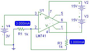
Fig. 1 Transconductance Amplifier. With vi = 3 and R1 = R3 = 1k and 1k
Now I saw the same voltage but with different resistance R1. See Fig.2

Fig. 2 Transconductance Amplifier. With vi = 3 and R1 = R3 = 1k 2.2ky
Now if we let R1 R3 the same but change:

Fig. 3 Transconductance Amplifier. With vi = 3 and R1 = R3 = 3k 2.2ky
course, the setting has a limit.
We must Rlmax = (Volmax - Vi) / IL, Rlmax = (Vcc - Vi) / IL,
and substituting IL we can say that:
Rlmax = (Vcc - Vi) * R / Vi, or Rlmax = (Vcc / Vi - 1 ) * R
RL in this case would be:
Rlmax = (Vcc / Vi - 1) * R1
Rlmax = (15 / 3 - 1) 1k
Rlmax = 4k
Then with values \u200b\u200bgreater than the 4k transconductance is no longer true. So if we add a R3 = 10k, the current will vary.

Fig. 4 Amplifier Transconductance. With vi = 3 and R1 = R3 = 1k and 10k
The difference is very small but as they increase the R3, the current increase.
2. Voltage converter with constant current grounded load

whereas the feedback is more negative than positive, the system is stable and can observe a virtual short circuit at the entrances of the OPAMP.
The analysis in this setting is very similar to the floating charge. The current through IRF1 = IRF2, so
(VI - VL) / RF1 = (VL - Vo) / Vo = VL factoring RF2 - (-RF1/RI1) (VI - VL)
IL = IF2 - II2, IL = (Vo - VL) / RF2 - VL / R I2
Vo Substituting in the equation of IL are:
IL = - (RF1/RI1 x RF2) x Vi + (RF1/RI1 x RF2 - 1 / RI2) x VL
In this last expression depends on IL VL, we must make this term zero so as not to depend on other voltages.
As VL = 0 if we
(RF1/RI1 x RF2 - 1 / RI2) x VL RF1/RI1 x RF2 = 1 / RI2 RF1/RI1 = RF2/RI2
then this equation would only
IL = - (RF1/RI1 x RF2) x Vi but as RF1 = RF2 x RI1/RI2 IL = (-1/RI2) Vi
An example would be: IL = - (1/5k) 5v IL = 1 mA, See Figure 5
R2 = RL; RI2 = R7
 Fig. 4 Transconductance Amplifier. With vi = 5 and RL = 1 and RI 2 = 5k
 Mario Dominguez Zambrano
EES Section: 02
0 comments:
Post a Comment