The technology used in TTL circuits is the basically use transistors and some other elements and devices. A transistor is a semiconductor electronic device (semiconductor is a substance that behaves like a conductor or an insulator depending on the electric field that is the most commonly used semiconductor is silicon) that acts as amplifier, oscillator, switch or rectifier.
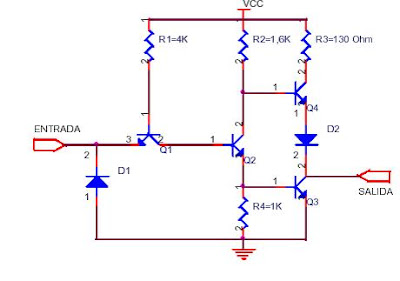
following circuit is the construction of a TTL inverter
The basic function of an inverter is as its name suggests, invests the state that reach the entrance, for example: if-inlet comes a logical 1 output is going to give us a logical 0 and vice versa.
The circuit description is as follows:
The transistor marked on the diagram as Q1 is in charge attaching the input function diode D1 is to set the input level, the transistor Q2 is a phase splitter, Q3 and Q4 form combining the output circuit.
The name that is used commercially for the investor is NOT Gate and electric represtación is:

the standard TTL family more used to a NOT gate is 74LS04

OR gate (standard TTL: 74LS32)
The OR gate is also at least two falls das and logical operation is the sum between the two, only when 1 + 1 = 1.

For a better understanding of this gate, we use an array of switches and B as many and stra in figure below.

Buffer (standard TTL: 74LS17)
The buffer does not actually perform any logical operation, its purpose is to amplify the signal a bit. As you can see in the chart below the output signal is the same input.

Applications:
- The TTL technology is currently used in the construction of:
- Microprocessors
- RAM Memory
- PROM
- PAL (Programmable Array Logic , consisting of a PROM inputs and interconnects number of logic gates).
BIBLIOGRAPHY:
- http://www.monografias.com/trabajos12/ttl/ttl.shtml
- http://es.wikipedia.org/wiki/Tecnolog% C3% ADa_TTL
- http://www.unicrom.com/ElectronicaDigital.asp
- http:// es.wikipedia.org / wiki / Transistor
- Workshop on Digital Circuits and Microprocessors, Volume 2
AUTHORS:
BENJAMIN GARCIA CORREA
JESUS \u200b\u200bGUZMAN CARMONA
DILERY

0 comments:
Post a Comment